

【H3C模拟器】动态路由协议与路由器实现Telnet服务
发布于2021-05-30 20:56 阅读(630) 评论(0) 点赞(21) 收藏(5)
之前发布了【H3C模拟器】静态路由与路由器实现Telnet服务 的文章,现在来还愿了。后续的实验就开始了,动态路由协议的RIP协议和OSPF协议,就在本章介绍了。
这里有个 Host 服务器主机:50.0.0.1/24。是需要在 Oracle VM VirtualBox 管理器中创建 虚拟操作系统 的,操作系统的自身的网卡要设置为仅主机模式,并配置相应的IP地址以及相对应的交换机和路由器的网关。(其实跟在 Vmware WorkStation 创建虚拟机一个道理)才能在HCL中使用。Host 服务器主机其实可以更好的贴近生产环境,不过只是进行实验,可以不怎么需要配置Host 服务器主机。
实验环境

首先介绍该实验不动的配置信息:两台PC机(PCA,PCB)
PCA 的配置:

PCB 的配置:
打开 Oracle VM VirtualBox,新建 => 新建虚拟电脑 => 使用ISO格式的操作系统镜像。后面就以同学的实际环境操作。这里就不做演示了。

本机创建了一台 Ubuntu 2004 操作系统。 注意:网卡需要设置为仅主机(Host-Only)模式。并且将 Ubuntu 2004 的 IP地址设置为 50.0.0.1/24,这样就可以使用该主机了。在HCL中,就会找 Oracle VM VirtualBox 的主机是否有 50.0.0.1/24 IP地址的主机,有的话,就会自动接到 Host 主机中。


RIP 动态路由的实验操作:
RIP(Routing Information Protocol,路由信息协议)就是最典型的距离矢量路由协议,常用于在小型网络钟交互路由信息,它是最先得到广泛使用的IGP(内部网关协议:在自治系统AS内部使用的路由协议),由于其工作机制相对简单。
目前RIP存在三个版本,分别是面向IPv4的RIPv1和RIPv2以及面向IPv6的RIPng。
RTA 的配置:
配置 RTA 的端口 IP 地址:
<H3C>system-view
System View: return to User View with Ctrl+Z.
[H3C]sysname Router-RTA
[Router-RTA]
[Router-RTA]interface GigabitEthernet 0/0
[Router-RTA-GigabitEthernet0/0]ip address 10.0.0.2 24
[Router-RTA-GigabitEthernet0/0]quit
[Router-RTA]interface GigabitEthernet 0/1
[Router-RTA-GigabitEthernet0/1]ip address 20.0.0.1 24
[Router-RTA-GigabitEthernet0/1]quit
配置 RTA 的 RIP 动态路由协议:
[Router-RTA]rip
[Router-RTA-rip-1]version ?
INTEGER<1-2> RIP version[Router-RTA-rip-1]version 2
[Router-RTA-rip-1]network 10.0.0.0?
X.X.X.X Network number[Router-RTA-rip-1]network 10.0.0.0
[Router-RTA-rip-1]network 20.0.0.0
查看 RTA 的 RIP 动态路由协议:
[Router-RTA]display rip 1 database
10.0.0.0/8, auto-summary
10.0.0.0/24, cost 0, nexthop 10.0.0.2, RIP-interface
20.0.0.0/8, auto-summary
20.0.0.0/24, cost 0, nexthop 20.0.0.1, RIP-interface
30.0.0.0/8, auto-summary
30.0.0.0/8, cost 1, nexthop 20.0.0.2
40.0.0.0/8, auto-summary
40.0.0.0/8, cost 2, nexthop 20.0.0.2
50.0.0.0/8, auto-summary
50.0.0.0/8, cost 3, nexthop 20.0.0.2
RTB 的配置:
配置 RTB 的端口 IP 地址:
<H3C>system-view
System View: return to User View with Ctrl+Z.
[H3C]sysname Router-RTB
[Router-RTB]
[Router-RTB]interface GigabitEthernet 0/0
[Router-RTB-GigabitEthernet0/0]ip address 30.0.0.1 24
[Router-RTB-GigabitEthernet0/0]quit
[Router-RTB]interface GigabitEthernet 0/1
[Router-RTB-GigabitEthernet0/1]ip address 20.0.0.2 24
[Router-RTB-GigabitEthernet0/1]quit
配置 RTB 的 RIP 动态路由协议:
[Router-RTB]rip
[Router-RTB-rip-1]version 2
[Router-RTB-rip-1]network 20.0.0.0
[Router-RTB-rip-1]network 30.0.0.0
查看 RTB 的 RIP 动态路由协议:
[Router-RTB]display rip 1 database
10.0.0.0/8, auto-summary
10.0.0.0/8, cost 1, nexthop 20.0.0.1
20.0.0.0/8, auto-summary
20.0.0.0/24, cost 0, nexthop 20.0.0.2, RIP-interface
30.0.0.0/8, auto-summary
30.0.0.0/24, cost 0, nexthop 30.0.0.1, RIP-interface
40.0.0.0/8, auto-summary
40.0.0.0/8, cost 1, nexthop 30.0.0.2
50.0.0.0/8, auto-summary
50.0.0.0/8, cost 2, nexthop 30.0.0.2
RTC 的配置:
配置 RTC 的端口 IP 地址:
<H3C>system-view
System View: return to User View with Ctrl+Z.
[H3C]sysname Router-RTC
[Router-RTC]
[Router-RTC]interface GigabitEthernet 0/0
[Router-RTC-GigabitEthernet0/0]ip address 30.0.0.2 24
[Router-RTC-GigabitEthernet0/0]quit
[Router-RTC]interface GigabitEthernet 0/1
[Router-RTC-GigabitEthernet0/1]ip address 40.0.0.1 24
[Router-RTC-GigabitEthernet0/1]quit
配置 RTC 的 RIP动态路由协议:
[Router-RTC]rip
[Router-RTC-rip-1]version 2
[Router-RTC-rip-1]network 30.0.0.0
[Router-RTC-rip-1]network 40.0.0.0
[Router-RTC-rip-1]quit
查看 RTC 的 RIP 动态路由协议:
[Router-RTC]display rip 1 database
10.0.0.0/8, auto-summary
10.0.0.0/8, cost 2, nexthop 30.0.0.1
20.0.0.0/8, auto-summary
20.0.0.0/8, cost 1, nexthop 30.0.0.1
30.0.0.0/8, auto-summary
30.0.0.0/24, cost 0, nexthop 30.0.0.2, RIP-interface
40.0.0.0/8, auto-summary
40.0.0.0/24, cost 0, nexthop 40.0.0.1, RIP-interface
50.0.0.0/8, auto-summary
50.0.0.0/8, cost 1, nexthop 40.0.0.2
RTD 的配置:
配置 RTD 的端口 IP 地址:
<H3C>system-view
System View: return to User View with Ctrl+Z.
[Router-RTD]interface GigabitEthernet 0/1
[Router-RTD-GigabitEthernet0/1]ip address 40.0.0.2 24
[Router-RTD-GigabitEthernet0/1]quit
[Router-RTD]interface GigabitEthernet 0/0
[Router-RTD-GigabitEthernet0/0]ip address 50.0.0.2 24
[Router-RTD-GigabitEthernet0/0]quit
配置 RTD 的 RIP动态路由协议:
[Router-RTD]rip
[Router-RTD-rip-1]version 2
[Router-RTD-rip-1]network 40.0.0.0
[Router-RTD-rip-1]network 50.0.0.0
查看 RTD 的 RIP 动态路由协议:
[Router-RTD]display rip 1 database
10.0.0.0/8, auto-summary
10.0.0.0/8, cost 3, nexthop 40.0.0.1
20.0.0.0/8, auto-summary
20.0.0.0/8, cost 2, nexthop 40.0.0.1
30.0.0.0/8, auto-summary
30.0.0.0/8, cost 1, nexthop 40.0.0.1
40.0.0.0/8, auto-summary
40.0.0.0/24, cost 0, nexthop 40.0.0.2, RIP-interface
50.0.0.0/8, auto-summary
50.0.0.0/24, cost 0, nexthop 50.0.0.2, RIP-interface
PC1 ping 通 PC2
如果不通,可以逐个检查一下设备的路由表,看一下有没有学习到RIP的动态路由协议。

RTD 路由器上做 Telnet 服务器
1.1 密码登录
[Router-RTD]telnet server enable
[Router-RTD]user-interface vty ?(user-interface 是指用户界面)
INTEGER<0-63> Number of the first line[Router-RTD]user-interface vty 0 4(全称为Virtual Teletype Terminal,指虚拟终端。不带vty的,就是实实在在的端口。0是初始值,4是结束值。表示可同时打开5个会话,进入交换机去配置命令,并且使用的配置都是一样的。)
[Router-RTD-line-vty0-4]authentication-mode ?(使用何种认证类型)
none Login without authentication
password Password authentication
scheme Authentication use AAA
[Router-RTD-line-vty0-4]authentication-mode password(使用密码登录认证)[Router-RTD-line-vty0-4]set authentication password simple 123456(设置密码)
1.2 测试密码登录

2.1 用户名 + 密码登录
# 创建用户
[Router-RTD]local-user h3c
[Router-RTD-luser-manage-h3c]password simple 123456
[Router-RTD-luser-manage-h3c]service-type ?
ftp FTP service
http HTTP service type
https HTTPS service type
pad X.25 PAD service
ssh Secure Shell service
telnet Telnet service
terminal Terminal access service[Router-RTD-luser-manage-h3c]service-type telnet(用户设置 telnet 服务)
[Router-RTD]user-interface vty 0 4
[Router-RTD-line-vty0-4]authentication-mode ?
none Login without authentication
password Password authentication
scheme Authentication use AAA[Router-RTD-line-vty0-4]authentication-mode scheme
[Router-RTD-line-vty0-4]user-role level-3(设置登录用户权限)
2.2 测试用户名 + 密码登录

OSPF 动态路由的实验操作:
要在路由器上配置OSPF,必须首先进入系统视图,然后执行ospf [ process-id | router-id router-id]命令以使能OSPF进程,并且进入OSPF视图。
执行ospf 命令时,如果不输入 process-id (该参数表示OSPF进程编号)的值,则 process-id 默认取值为1。router-id是一共32比特的二进制数,也经常表示为点分十进制数。如果在执行ospf 命令时不指定router-id,则路由器会根据某种规则自动生成一个值来作为router-id。
[Router-RTA]ospf ?
INTEGER<1-65535> Process ID
mib-binding Bind MIB to an OSPF process
router-id OSPF Private Router ID
vpn-instance VPN instance
<cr>
(1)process-id为进程号,缺省值为1。
路由器支持OSPF多进程,可以根据业务类型划分不同的进程。进程号是本地概念,不影响与其它路由器之间的报文交换。因此,不同的路由器之间,即使进程号不同也可以进行报文交换。
(2)router-id router-id为路由器的ID号。
缺省情况下,路由器系统会从当前接口的IP地址中自动选取一个最大值作为Router ID。手动配置Router ID时,必须保证自治系统中任意两台Router ID都不相同。通常的做法是将Router ID配置为与该设备某个接口的IP地址一致
说明:
每个OSPF进程的Router ID要保证在OSPF网络中唯一,否则会导致邻居不能正常建立、路由信息不正确的问题。建议在OSPF设备上单独为每个OSPF进程配置全网唯一的Router ID。
(3)vpn-instance vpn-instance-name表示VPN实例。
如果指定了VPN实例,那么此OSPF进程属于指定的VPN实例,如果未指定则属于公网实例。
(4)area id
区域是从逻辑上将设备划分为不同的组,每个组用区域号(AreaID)来标识。区域的边界是设备,而不是链路。一个网段(链路)只能属于一个区域,或者说每个运行OSPF的接口必须指明属于哪一个区域。
因为 OSPF 比较试用于大型的网络,所以我们可以改造一下这个拓扑图。打算将静态路由,动态路由,设备之间的堆叠,以及设备telnet的使用。汇聚在一块。
要求(实现没有先后顺序,只要能达到就行):
1.在Router-01的区域主机之间相互ping通,即PC-A,PC-B 可以ping通,外部网络可以相互ping通,即PC-C,PC-D,PC-E,Server 1可以相互ping通。
2.SW-C和SW-D使用静态路由到Area 1和Area 2
3.使用OSPF(Area 0 ,Area 1 ,Area 2 ,Area 3,Area 4)将整个网络架构连接起来
4.SW-A和SW-B ,SW-C和SW-D使用堆叠技术
5.Server1可以 telnet Router-02

顺序本人是打乱的,大家做实验可以先按自己的方式进行配置。
| 设备 | 接口名称 | 接口IP地址 |
| Switch-A-Master(Switch-B-Slave) | GE1/0/1(To:PC-A) | Vlan-Interface 10:10.0.0.254/24 |
| GE1/0/2(To:Router-01) | Vlan-Interface 1010:10.0.10.1/24 | |
| GE2/0/1(To:PC-B) | Vlan-Interface 20:20.0.0.254/24 | |
| GE2/0/2(To:Router-01) | Vlan-Interface 1020:20.0.10.1/24 | |
| Router-01 | GE0/0(To:Switch-C-Master) | 192.168.20.1/24 |
|
| GE0/1(To:Switch-A-Master) | 10.0.10.2/24 |
| GE0/2(To:Switch-B-Slave) | 20.0.10.2/24 | |
| Switch-C-Master(Switch-D-Slave) | GE1/0/1(To:Router-01) | Vlan-Interface 1920:192.168.20.2/24 |
| GE1/0/2(To:Router-04) | Vlan-Interface 1910:192.168.10.2/24 | |
| GE2/0/1(To:Router-05) | Vlan-Interface 1710:172.31.10.2/24 | |
| GE2/0/2(To:Router-02) | Vlan-Interface 1720:172.31.20.1/24 | |
| Router-02 | GE0/0(To:Switch-D-Slave) | 172.31.20.2/24 |
| GE0/1(To:PC-C) | 40.0.0.2/24 | |
| GE0/2(To:Server1) | 50.0.0.2/24 | |
| Router-03 | GE0/1(To:PC-D) | 192.168.1.254/24 |
| GE0/2(To:Router-04) | 192.168.2.1/24 | |
| Router-04 | GE0/1(To:Switch-C-Master) | 192.168.10.1/24 |
| GE0/2(To:Router-03) | 192.168.2.2/24 | |
| Router-05 | GE0/1(To:Switch-D-Slave) | 172.31.10.1/24 |
| GE0/2(To:Router-06) | 172.31.2.2/24 | |
| Router-06 | GE0/1(To:PC-E) | 172.31.1.254/24 |
| GE0/2(To:Router-05) | 172.31.2.1/24 |
| PC机名称 | IP地址 | 网关IP地址 |
| PC-A | 10.0.0.1/24 | 10.0.0.254/24 |
| PC-B | 20.0.0.1/24 | 20.0.0.254/24 |
| PC-C | 40.0.0.1/24 | 40.0.0.2/24 |
| PC-D | 192.168.1.1/24 | 192.168.1.254/24 |
| PC-E | 172.31.1.1/24 | 172.31.1.254/24 |
| Server1 | 50.0.0.1/24 | 50.0.0.2/24 |
1 配置交换机堆叠技术
1.1.将SW-A-Master交换机和SW-B-Slave交换机做堆叠(添加描述)
<H3C>system-view (加入到全局模式)
System View: return to User View with Ctrl+Z.[H3C]sysname Switch-A (设置交换机名称)
[Switch-A]interface range FGE1/0/53 to FGE1/0/54 (将 FGE1/0/53 和 FGE1/0/54 关闭接口,shutdown掉)
[Switch-A-if-range]shutdown
[Switch-A]irf-port 1/2 (设置 IRF 堆叠)
[Switch-A-irf-port1/2]port group interface FGE1/0/53 (添加接口)
You must perform the following tasks for a successful IRF setup:
Save the configuration after completing IRF configuration.
Execute the "irf-port-configuration active" command to activate the IRF ports.[Switch-A-irf-port1/2]port group interface FGE1/0/54(添加接口)
[Switch-A-irf-port1/2]display this (查看配置)
#
irf-port 1/2
port group interface FortyGigE1/0/53
port group interface FortyGigE1/0/54
#
return[Switch-A]interface range FortyGigE1/0/53 to FortyGigE1/0/54(将 FGE1/0/53 和 FGE1/0/54 开启接口,undo shutdown)
[Switch-A-if-range]undo shutdown
[Switch-A]irf member 1 priority 30 (设置优先级)
<Switch-A>save force (保存配置)
[Switch-A]irf-port-configuration active (激活 IRF 配置)
<H3C>system-view
System View: return to User View with Ctrl+Z.[H3C]sysname Switch-B
[Switch-B]interface range FGE1/0/53 to FGE1/0/54
[Switch-B-if-range]shutdown
[Switch-B]irf member 1 renumber 2
Renumbering the member ID may result in configuration change or loss. Continue?[Y/N]y<Switch-B>save force
<Switch-B>reboot
[Switch-B]interface range FGE2/0/53 to FGE2/0/54
[Switch-B-if-range]shutdown
[Switch-B]irf-port 2/1
[Switch-B-irf-port2/1]port group interface FGE2/0/53
You must perform the following tasks for a successful IRF setup:
Save the configuration after completing IRF configuration.
Execute the "irf-port-configuration active" command to activate the IRF ports.[Switch-B-irf-port2/1]port group interface FGE2/0/54
[Switch-B-irf-port2/1]quit
[Switch-B]int range FGE2/0/53 to FGE2/0/54
[Switch-B-if-range]undo shutdown
[Switch-B]irf member 2 priority 20
<Switch-B>save force
[Switch-B]irf-port-configuration active
检查并添加描述
[Switch-A]interface FGE1/0/53
[Switch-A-FortyGigE1/0/53]description Switch-A-IRF-INT
[Switch-A-FortyGigE1/0/53]quit[Switch-A]interface FGE1/0/54
[Switch-A-FortyGigE1/0/54]description Switch-A-IRF-INT
[Switch-A-FortyGigE1/0/54]quit
[Switch-A]interface FGE2/0/53
[Switch-A-FortyGigE2/0/53]description Switch-B-IRF-INT
[Switch-A-FortyGigE2/0/53]quit[Switch-A]interface FGE2/0/54
[Switch-A-FortyGigE2/0/54]description Switch-B-IRF-INT
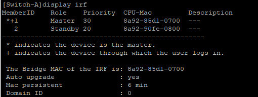
[Switch-A-FortyGigE2/0/54]quit[Switch-A]display irf
[Switch-A]display irf configuration
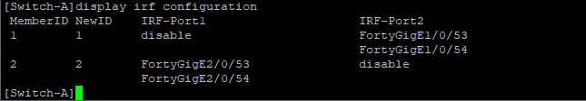

1.2.将SW-C-Master交换机和SW-D-Slave交换机做堆叠(添加描述)
<H3C>system-view
System View: return to User View with Ctrl+Z.[H3C]sysname Switch-C
[Switch-C]interface range FortyGigE1/0/53 to FortyGigE1/0/54
[Switch-C-if-range]shutdown
[Switch-C]irf-port 1/2
[Switch-C-irf-port1/2]port group interface FortyGigE1/0/53
You must perform the following tasks for a successful IRF setup:
Save the configuration after completing IRF configuration.
Execute the "irf-port-configuration active" command to activate the IRF ports.[Switch-C-irf-port1/2]port group interface FortyGigE1/0/54
[Switch-C-irf-port1/2]quit
[Switch-C]interface range FortyGigE1/0/53 to FortyGigE1/0/54
[Switch-C-if-range]undo shutdown
[Switch-C]irf member 1 priority 30
[Switch-C]save force[Switch-C]irf-port-configuratio
<H3C>system-view
System View: return to User View with Ctrl+Z.[H3C]sysname Switch-D
[Switch-D]irf member 1 renumber 2
Renumbering the member ID may result in configuration change or loss. Continue?[Y/N]y[Switch-D]save force
<Switch-D>reboot[Switch-D]interface range FGE2/0/53 to FGE2/0/54
[Switch-D-if-range]shutdown
[Switch-D]irf-port 2/1
[Switch-D-irf-port2/1]port group interface FGE2/0/53
You must perform the following tasks for a successful IRF setup:
Save the configuration after completing IRF configuration.
Execute the "irf-port-configuration active" command to activate the IRF ports.[Switch-D-irf-port2/1]port group interface FGE2/0/54
[Switch-D]interface range FGE2/0/53 to FGE2/0/54
[Switch-D-if-range]undo shutdown
[Switch-D-if-range]quit
[Switch-D]irf member 2 priority 20
[Switch-D]save force
[Switch-D]irf-port-configuration active
检查并添加描述
[Switch-C]interface FGE1/0/53
[Switch-C-FortyGigE1/0/53]description Switch-C-IRF-INT
[Switch-C-FortyGigE1/0/53]quit
[Switch-C]interface FGE1/0/54
[Switch-C-FortyGigE1/0/54]description Switch-C-IRF-INT
[Switch-C-FortyGigE1/0/54]quit
[Switch-C]interface FGE2/0/53
[Switch-C-FortyGigE2/0/53]description Switch-D-IRF-INT
[Switch-C-FortyGigE2/0/53]quit
[Switch-C]interface FGE2/0/54
[Switch-C-FortyGigE2/0/54]description Switch-D-IRF-INT
[Switch-C-FortyGigE2/0/54]quit[Switch-C]display irf
[Switch-C]display irf configuration


堆叠的部分就完成了,接着将拓扑图中的各个主机的IP地址进行配置。这部分就不做演示了。
2.交换机以及路由器之间的接口进行配置
Area 0区域的路由器以及交换机的配置:
<H3C>system-view
System View: return to User View with Ctrl+Z.[H3C]sysname Router-04
[Router-04]]interface GigabitEthernet 0/1
[Router-04-GigabitEthernet0/1]ip address 192.168.10.1 24[Router-04-GigabitEthernet0/1]description To:Switch-C-Master
[Router-04]interface GigabitEthernet 0/2
[Router-04-GigabitEthernet0/2]ip address 192.168.2.2 24
[Router-04-GigabitEthernet0/2]description To:Router-03
<H3C>system-view
System View: return to User View with Ctrl+Z.[H3C]sysname Router-05
[Router-05]interface GigabitEthernet 0/1
[Router-05-GigabitEthernet0/1]ip address 172.31.10.1 24
[Router-05-GigabitEthernet0/1]description To:Switch-D-Slave
[Router-05-GigabitEthernet0/1]quit
[Router-05]interface GigabitEthernet 0/2
[Router-05-GigabitEthernet0/2]ip address 172.31.2.2 24
[Router-05-GigabitEthernet0/2]description To:Router-06
[Router-05-GigabitEthernet0/2]quit
因为做了堆叠技术,所以 Switch-C 和 Switch-D 是一台设备,要在相对应的接口进行配置IP地址和划分VLAN(每设置一个接口之后,跟直连的设备进行ping操作)
[Switch-C]vlan 1920
[Switch-C-vlan1920]vlan 1910
[Switch-C-vlan1910]vlan 1710
[Switch-C-vlan1710]vlan 1720[Switch-C]interface Vlan-interface 1920
[Switch-C-Vlan-interface1920]ip address 192.168.20.2 24
[Switch-C-Vlan-interface1920]description To:Router-01
[Switch-C-Vlan-interface1920]quit
[Switch-C]interface Vlan-interface 1910[Switch-C-Vlan-interface1910]ip address 192.168.10.2 24
[Switch-C-Vlan-interface1910]description To:Router-04
[Switch-C-Vlan-interface1910]quit
[Switch-C]interface Vlan-interface 1710[Switch-C-Vlan-interface1710]ip address 172.31.10.2 24
[Switch-C-Vlan-interface1710]description To:Router-05
[Switch-C-Vlan-interface1710]quit
[Switch-C]interface Vlan-interface 1720[Switch-C-Vlan-interface1720]ip address 172.31.20.1 24
[Switch-C-Vlan-interface1720]description To:Router-02
[Switch-C-Vlan-interface1720]quit
[Switch-C]interface GigabitEthernet 1/0/1
[Switch-C-GigabitEthernet1/0/1]port link-type trunk
[Switch-C-GigabitEthernet1/0/1]port trunk pvid vlan 1920
[Switch-C-GigabitEthernet1/0/1]port trunk permit vlan all
[Switch-C-GigabitEthernet1/0/1]description To:Router-01
[Switch-C]interface GigabitEthernet 1/0/2
[Switch-C-GigabitEthernet1/0/2]port link-type trunk
[Switch-C-GigabitEthernet1/0/2]port trunk pvid vlan 1910
[Switch-C-GigabitEthernet1/0/2]port trunk permit vlan all
[Switch-C-GigabitEthernet1/0/2]description To:Router-04
[Switch-C]interface GigabitEthernet 2/0/1
[Switch-C-GigabitEthernet2/0/1]port link-type trunk
[Switch-C-GigabitEthernet2/0/1]port trunk pvid vlan 1720
[Switch-C-GigabitEthernet2/0/1]port trunk permit vlan all
[Switch-C-GigabitEthernet2/0/1]description To:Router-02
[Switch-C]interface GigabitEthernet 2/0/2
[Switch-C-GigabitEthernet2/0/2]port link-type trunk
[Switch-C-GigabitEthernet2/0/2]port trunk pvid vlan 1710
[Switch-C-GigabitEthernet2/0/2]port trunk permit vlan all
[Switch-C-GigabitEthernet2/0/2]description To:Router-05
Area 1区域的路由器的配置:
<H3C>system-view
System View: return to User View with Ctrl+Z.
[H3C]sysname Router-03[Router-03]interface GigabitEthernet 0/1
[Router-03-GigabitEthernet0/1]ip address 192.168.1.254 24
[Router-03-GigabitEthernet0/1]description To:PC-D
[Router-03-GigabitEthernet0/1]quit[Router-03]interface GigabitEthernet 0/2
[Router-03-GigabitEthernet0/2]ip address 192.168.2.1 24
[Router-03-GigabitEthernet0/2]description To:Router-04
[Router-03-GigabitEthernet0/2]quit
Area 2区域的路由器的配置:
<H3C>system-view
System View: return to User View with Ctrl+Z.
[H3C]sysname Router-06[Router-06]interface GigabitEthernet 0/1
[Router-06-GigabitEthernet0/1]ip address 172.31.1.254 24
[Router-06-GigabitEthernet0/1]description To:PC-E
[Router-06-GigabitEthernet0/1]quit
[Router-06]interface GigabitEthernet 0/2
[Router-06-GigabitEthernet0/2]ip address 172.31.2.1 24
[Router-06-GigabitEthernet0/2]description To:Router-05
[Router-06-GigabitEthernet0/2]quit
Area 3区域的路由器以及交换机的配置:
因为做了堆叠技术,所以 Switch-A 和 Switch-B 是一台设备,要在相对应的接口进行配置IP地址和划分VLAN(每设置一个接口之后,跟直连的设备进行ping操作)
[Switch-A]vlan 10 to 20
[Switch-A]interface Vlan-interface 10
[Switch-A-Vlan-interface10]ip address 10.0.0.254 24
[Switch-A]interface GigabitEthernet 1/0/1
[Switch-A-GigabitEthernet1/0/1]description To:PC-A
[Switch-A-GigabitEthernet1/0/1]port link-type access
[Switch-A-GigabitEthernet1/0/1]port access vlan 10
[Switch-A-GigabitEthernet1/0/1]ping 10.0.0.1
Ping 10.0.0.1 (10.0.0.1): 56 data bytes, press CTRL_C to break
56 bytes from 10.0.0.1: icmp_seq=0 ttl=255 time=3.000 ms[Switch-A]interface Vlan-interface 20
[Switch-A-Vlan-interface20]ip address 20.0.0.254 24
[Switch-A-Vlan-interface20]quit
[Switch-A]interface GigabitEthernet 2/0/1[Switch-A-GigabitEthernet2/0/1]description To:PC-B
[Switch-A-GigabitEthernet2/0/1]port link-type access
[Switch-A-GigabitEthernet2/0/1]ping 20.0.0.1
Ping 20.0.0.1 (20.0.0.1): 56 data bytes, press CTRL_C to break
56 bytes from 20.0.0.1: icmp_seq=0 ttl=255 time=5.000 ms[Switch-A]vlan 1010 to 1020
[Switch-A]interface Vlan-interface 1010
[Switch-A-Vlan-interface1010]ip address 10.0.10.1 24
[Switch-A-Vlan-interface1010]quit
[Switch-A]interface Vlan-interface 1020
[Switch-A-Vlan-interface1020]ip address 20.0.10.1 24
[Switch-A-Vlan-interface1020]quit[Switch-A]interface GigabitEthernet 1/0/2
[Switch-A-GigabitEthernet1/0/2]port link-type access
[Switch-A-GigabitEthernet1/0/2]port access vlan 1010
[Switch-A]interface GigabitEthernet 2/0/2
[Switch-A-GigabitEthernet2/0/2]port link-type access
[Switch-A-GigabitEthernet2/0/2]port access vlan 1020
Router-01 路由器配置:
<H3C>system-view
System View: return to User View with Ctrl+Z.[H3C]sysname Router-01
[Router-01]interface GigabitEthernet 0/1
[Router-01-GigabitEthernet0/1]ip address 10.0.10.2 24
[Router-01-GigabitEthernet0/1]description Switch-A-Master
[Router-01]interface GigabitEthernet 0/2
[Router-01-GigabitEthernet0/2]ip address 20.0.10.2 24[Router-01-GigabitEthernet0/2]description Switch-B-Slave
[Router-01]interface GigabitEthernet 0/0
[Router-01-GigabitEthernet0/0]ip address 192.168.20.1 24[Router-01-GigabitEthernet0/0]description Switch-C-Master
Area 4区域的路由器的配置:
<H3C>system-view
System View: return to User View with Ctrl+Z.[H3C]sysname Router-02
[Router-02]interface GigabitEthernet 0/0
[Router-02-GigabitEthernet0/0]ip address 172.31.20.2 24
[Router-02-GigabitEthernet0/0]quit
[Router-02]interface GigabitEthernet 0/1
[Router-02-GigabitEthernet0/1]ip address 40.0.0.2 24
[Router-02-GigabitEthernet0/1]quit
[Router-02]interface GigabitEthernet 0/2
[Router-02-GigabitEthernet0/2]ip address 50.0.0.2 24
[Router-02-GigabitEthernet0/2]quit
SW-C和SW-D使用静态路由到Area 1和Area 2
因为做了堆叠技术,所以 Switch-C 和 Switch-D 是一台设备,只要配置相应的静态路由即可。当然其实后面的OSPF动态路由也可以实现。
这里为了巩固其静态路由的工作原理。检验的方式就是Switch-C可以ping通PC-E,PC-D
路由器配置静态路由:
Router-03,Router-04,Router-05,Router-06配置静态路由
[Router-03]ip route-static 192.168.10.0 24 192.168.2.2
[Router-04]ip route-static 192.168.1.0 24 192.168.2.1
[Router-05]ip route-static 172.31.1.0 24 172.31.2.1
[Router-06]ip route-static 172.31.10.0 24 172.31.2.2
交换机配置静态路由:
Switch-C 配置静态路由
[Switch-C] ip route-static 172.31.1.0 24 172.31.10.1
[Switch-C] ip route-static 172.31.2.0 24 172.31.10.1
[Switch-C] ip route-static 192.168.1.0 24 192.168.10.1
[Switch-C] ip route-static 192.168.2.0 24 192.168.10.1
检验:Switch-C可以ping通PC-E,PC-D

使用OSPF将整个网络架构连接起来
可以看出使用静态路由配置比较大型的网络会显得十分吃力,这个时候就需要使用动态路由协议来帮助网络工程师实现网络的互联互通。使用OSPF动态路由协议将网络结构连接起来。注意使用OSPF时,需要使用反掩码。
路由器Router-01,Router-02,Router-03,Router-04,Router-05,Router-06分别对应OSPF中Router-id的1.1.1.1,2.2.2.2,3.3.3.3,4.4.4.4,5.5.5.5,6.6.6.6。
交换机SW-A-Master,SW-C-Master分别对应OSPF中Router-id的11.11.11.11,22.22.22.22。当然OSPF有时候也是需要跟静态路由配合使用。
OSPF Area 0 区域:
[Switch-C]ospf 1
[Switch-C-ospf-1]display this
#
ospf 1 router-id 22.22.22.22
area 0.0.0.0
network 172.31.10.0 0.0.0.255
network 192.168.10.0 0.0.0.255
area 0.0.0.3
network 192.168.20.0 0.0.0.255
area 0.0.0.4
network 172.31.20.0 0.0.0.255
area 0.0.0.5
network 10.0.0.0 0.0.0.255
area 0.0.0.6
network 20.0.0.0 0.0.0.255
#
return[Router-04]ospf 1
[Router-04-ospf-1]display this
#
ospf 1 router-id 4.4.4.4
area 0.0.0.0
network 192.168.10.0 0.0.0.255
area 0.0.0.1
network 192.168.2.0 0.0.0.255
#
return[Router-05]ospf 1
[Router-05-ospf-1]display this
#
ospf 1 router-id 5.5.5.5
area 0.0.0.0
network 172.31.10.0 0.0.0.255
area 0.0.0.2
network 172.31.2.0 0.0.0.255
#
return
OSPF Area 1 区域:
[Router-03]ospf 1 router-id 3.3.3.3
[Router-03-ospf-1]area 1
[Router-03-ospf-1-area-0.0.0.1]network 192.168.1.0 0.0.0.255
[Router-03-ospf-1-area-0.0.0.1]network 192.168.2.0 0.0.0.255
OSPF Area 2 区域:
[Router-06]ospf 1 router-id 6.6.6.6
[Router-06-ospf-1]area 2
[Router-06-ospf-1-area-0.0.0.2]network 172.31.1.0 0.0.0.255
[Router-06-ospf-1-area-0.0.0.2]network 172.31.2.0 0.0.0.255
OSPF Area 3 区域:
[Router-01]ospf 1
[Router-01-ospf-1]display this
#
ospf 1 router-id 1.1.1.1
area 0.0.0.0
network 192.168.20.0 0.0.0.255
area 0.0.0.3
network 10.0.10.0 0.0.0.255
network 20.0.10.0 0.0.0.255
#
return
OSPF Area 4 区域:
[Router-02]ospf 1 router-id 2.2.2.2
[Router-02-ospf-1]area 4
[Router-02-ospf-1-area-0.0.0.4]network 40.0.0.0 0.0.0.255
[Router-02-ospf-1-area-0.0.0.4]network 50.0.0.0 0.0.0.255
[Router-02-ospf-1-area-0.0.0.4]network 172.31.20.0 0.0.0.255
OSPF Area 5 Area 6区域:
[Switch-A]ospf 1
[Switch-A-ospf-1]display this
#
ospf 1 router-id 11.11.11.11
area 0.0.0.3
network 10.0.10.0 0.0.0.255
network 20.0.10.0 0.0.0.255
area 0.0.0.5
network 10.0.0.0 0.0.0.255
area 0.0.0.6
network 20.0.0.0 0.0.0.255
#
return
PC-A 和 PC-B互通

PC-C与Server 1 PC-E,PC-D互通


Server1可以telnet Router-02
1.1 密码登录
[Router-02]ssh server enable
[Router-02]telnet server enable
[Router-02]user-interface vty 0 4
[Router-02-line-vty0-4]authentication-mode password
[Router-02-line-vty0-4]set authentication password simple 123456
1.2 测试密码登录

2.1 用户名 + 密码登录(telnet)
# 创建用户
[Router-02]local-user h3c
New local user added.
[Router-02-luser-manage-h3c]password simple 123456
[Router-02-luser-manage-h3c]service-type ssh telnet[Router-02]user-interface vty 0 4
[Router-02-line-vty0-4]authentication-mode ?
none Login without authentication
password Password authentication
scheme Authentication use AAA[Router-02-line-vty0-4]authentication-mode scheme
[Router-02-line-vty0-4]user-role level-3(设置登录用户权限)
2.2 测试用户名 + 密码登录

所属网站分类: 技术文章 > 博客
作者:门路弄土了吗
链接:http://www.phpheidong.com/blog/article/86927/a450b4b194eb28f35db3/
来源:php黑洞网
任何形式的转载都请注明出处,如有侵权 一经发现 必将追究其法律责任
昵称:
评论内容:(最多支持255个字符)
---无人问津也好,技不如人也罢,你都要试着安静下来,去做自己该做的事,而不是让内心的烦躁、焦虑,坏掉你本来就不多的热情和定力